Overview
Class: GE 5030 Iterative Product Prototyping for Engineers Project #1
For my first class project, I had to create a test bed for extension springs. The product would be used in a lab setting, where TAs would be teaching students how to experimentally determine the k value of a spring. It needs to be self balancing on a table without adhesives, and the methods of prototyping were limited to laser cutting and 3D printing.
Design Process
Specifications
‣ Usability/Readability: The test bed should focus on setup and used to test the different available springs
‣ Fabrication Speed and Material Usage: The design should efficiently use laser cutting and attempt to limit excess material usage
‣ Aesthetics/Style: The design should be clean or follow a style
Prototype Iteration #1
When I was forming my initial design ideas, I put a strong focus on user experience. I wanted the design to be collapsible to reduce the amount of storage space needed for the test beds. I knew that the measuring plate would be the longest piece of the design, so I made turned it into a 2-piece design that could be connected by a pin. In my proof of concept, I used a Sharpie marker to hold two cardboard plates together, shown on the right.
In the initial tests, the spring bed was able to suspend a spring and measure the displacement after a weight was added. I noticed the panels were prone to leaning to one side, so I noted that I should improve the stability for the next design.
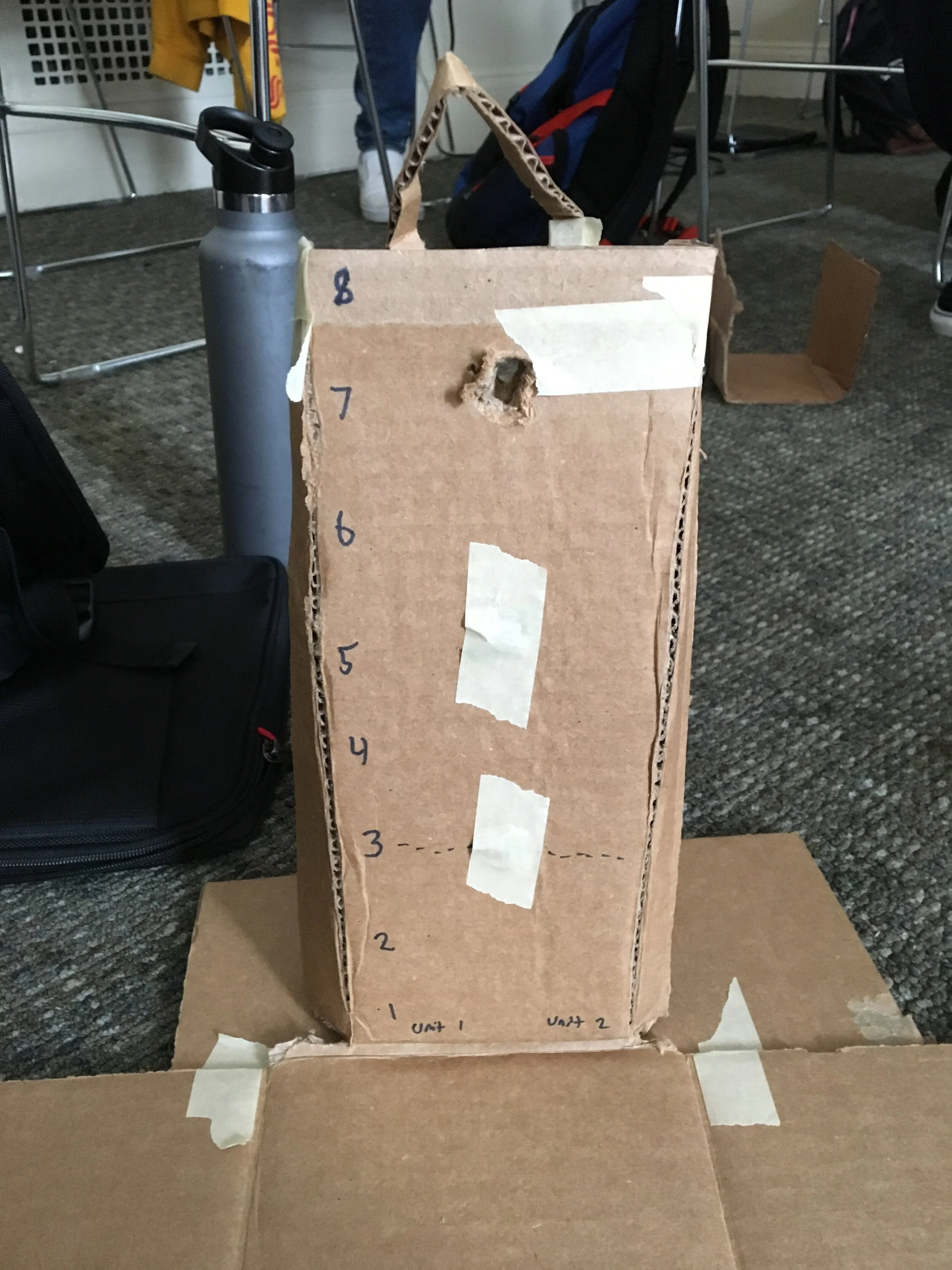
Spring bed (unextended)
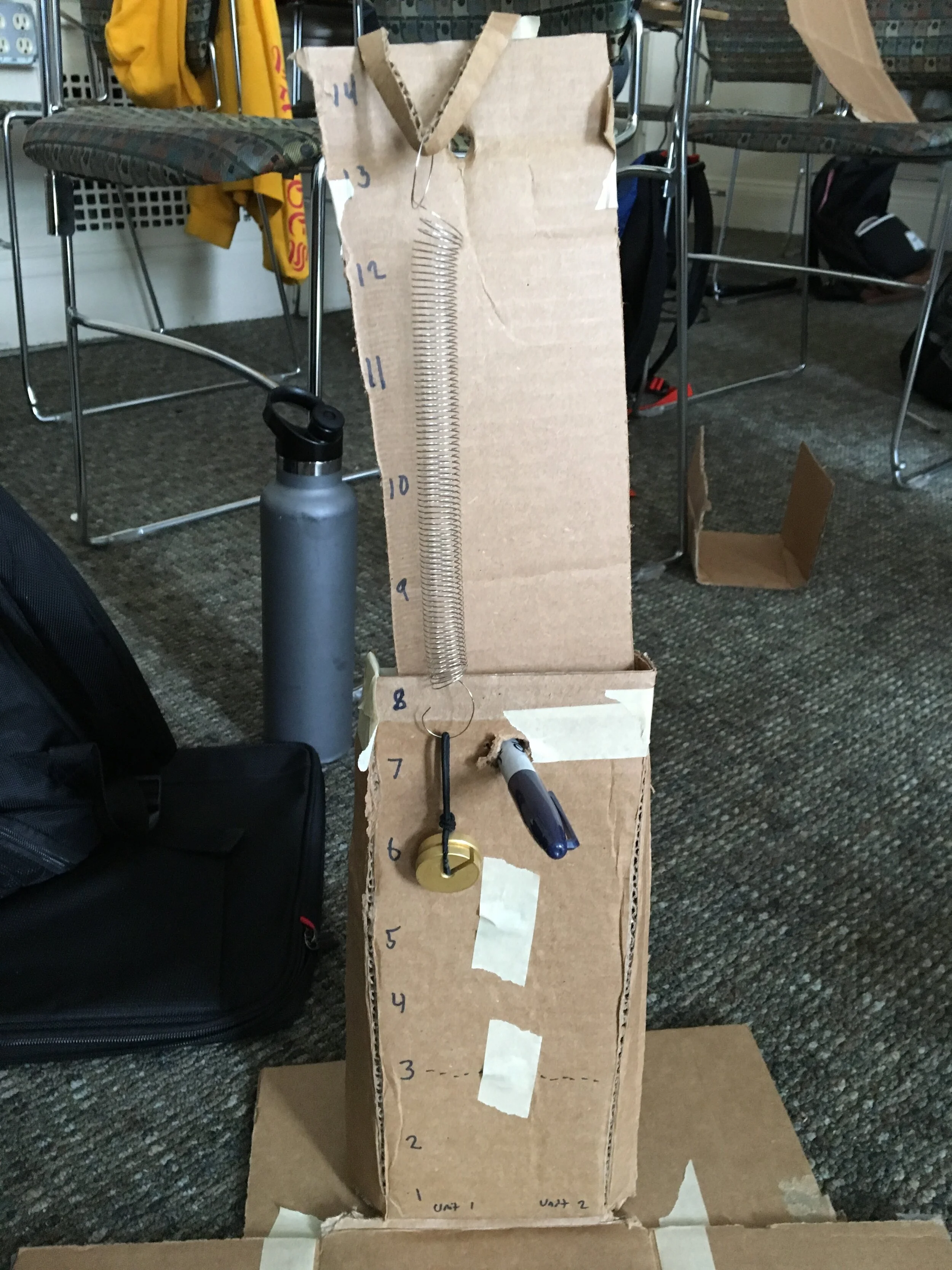
Spring Test Bed (Extended)
Prototype Iteration #2
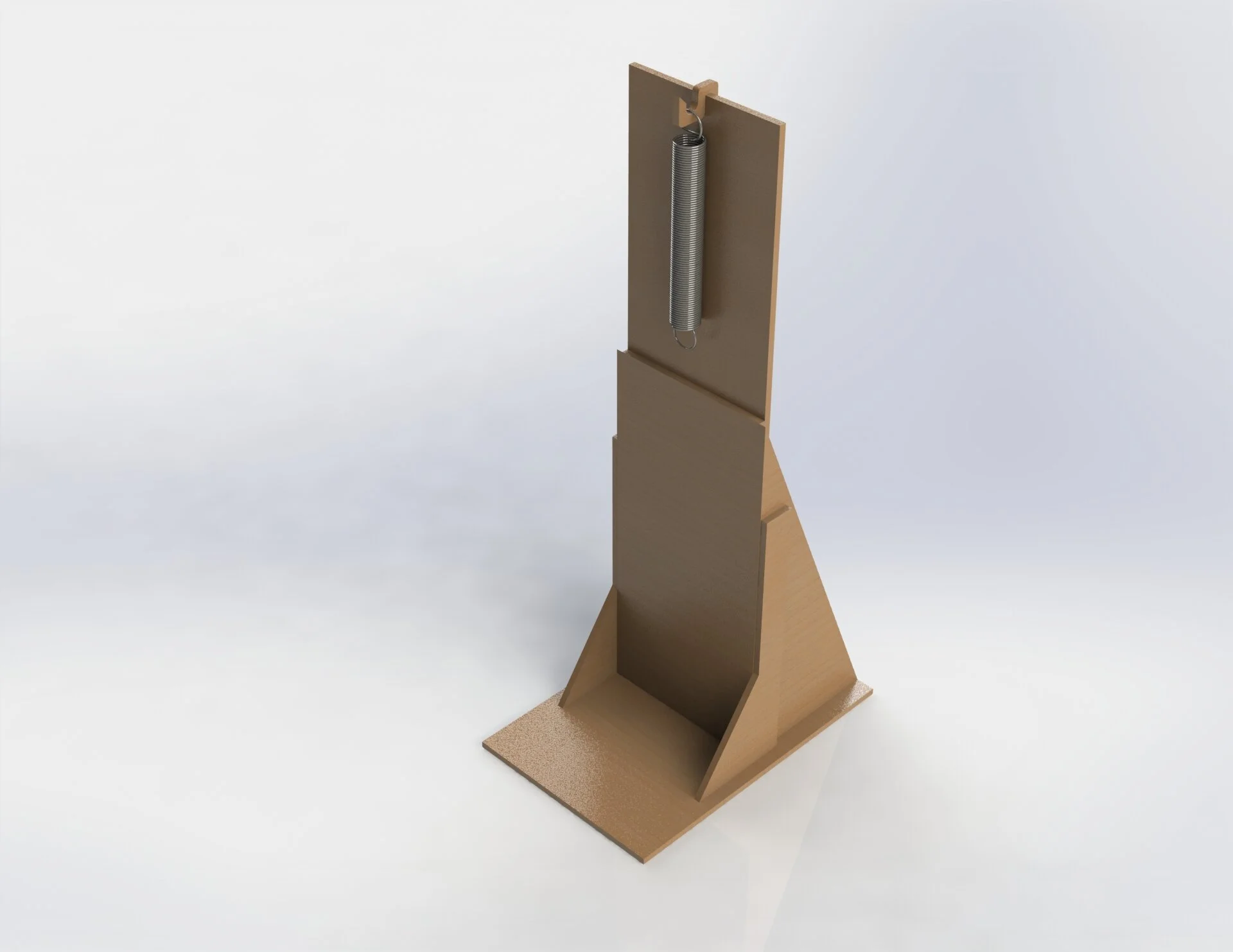
I utilized puzzle pieces for the second design so it can be easily assembled, disassembled, and stored away. This would reduce the cost and complexity added by introducing hardware like screws. I originally designed my assembly in SOLIDWORKS so I can see how the pieces fitted together. I decided to fabricate the parts with laser cutting instead of 3D printing to take advantage of the uniform thickness and simplicity of the pieces. Also, laser cutting was cheaper and had a shorter lead time.
On the bottom left image, these were the main components of the test bed. They consist of the base, hook, and measuring panel with blue score marks for inches and centimeters. On the right, these were pieces used to support the overall structure.


Testing and Feedback
On testing day, I had four students try to assemble and operate the device. I quickly realized that I did not make the assembly order intuitive enough as none of the students were able to assemble the testing bed together without a manual. Despite the initial hurtle, the students were satisfied with the experience of using the device. They mainly noted the “cool” design and ease of use when measuring. Something I noticed, though, was that the testing bed started to bend as the weights got heavier. Since the load was offset from the vertical axis, the testing panel acted like a cantilever. I ran a simulation of the testing bed on SOLIDWORKS and found that the panel deflects 1.5mm with 5 pounds. To make the device as accurate as possible, I would have to reduce the deflection by either fixing the ends, increasing the thickness, or changing the material.


